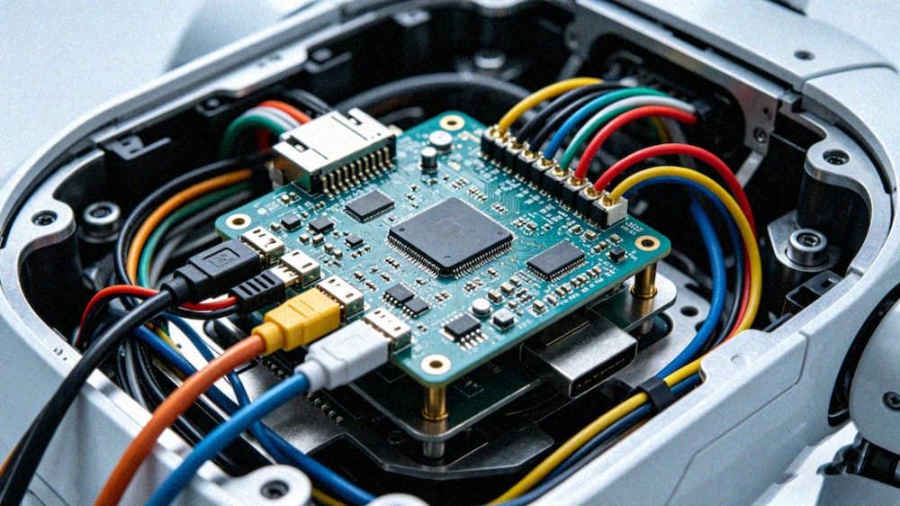
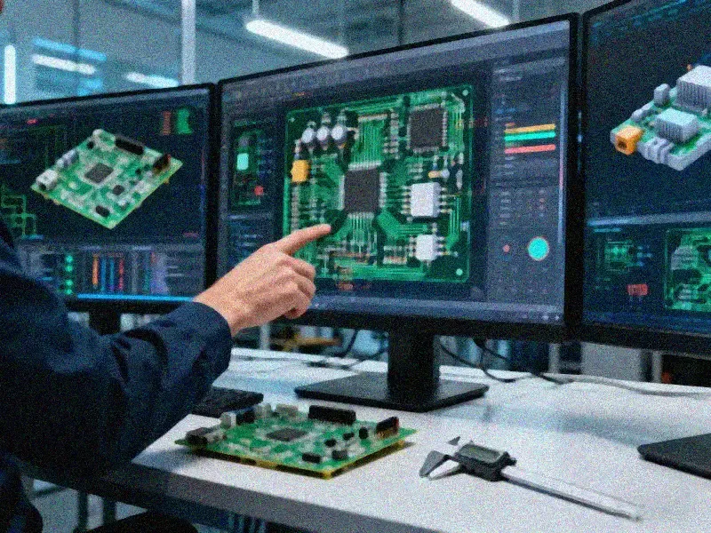
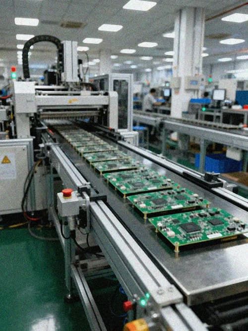
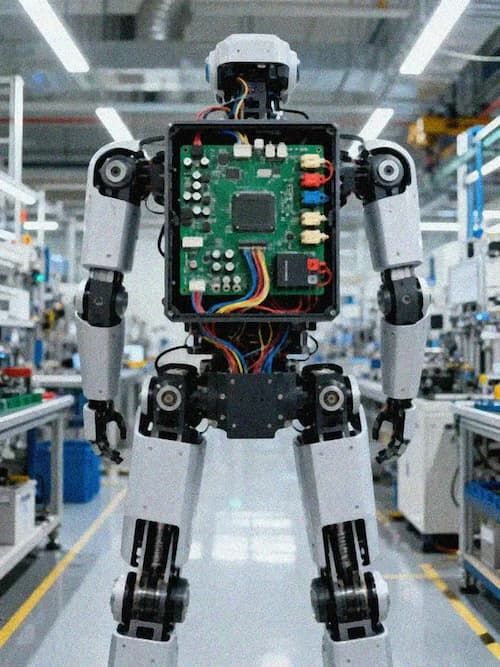
As humanoid robots move from laboratory prototypes to industrial mass production, the stability and computing power density of the core control system have become key bottlenecks restricting performance breakthroughs. Under the complex electromagnetic environment and high power density requirements, the humanoid robot PCB control solution based on the RK3588 core board not only needs to provide powerful AI computing capabilities, but also needs to solve the severe challenges of signal integrity (SI) and power integrity (PI) at the AI embedded system PCB design level. Industry data shows that thermal management and high-speed signal transmission loss of high-performance computing units are core pain points before mass production. Any tiny impedance discontinuity or power supply noise may cause an increase in the system bit error rate and affect the robot's motion control accuracy.
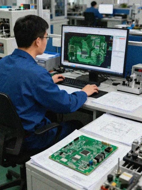
Quantitative analysis of core computing power architecture and NPU performance
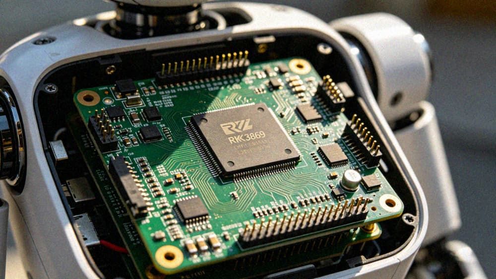
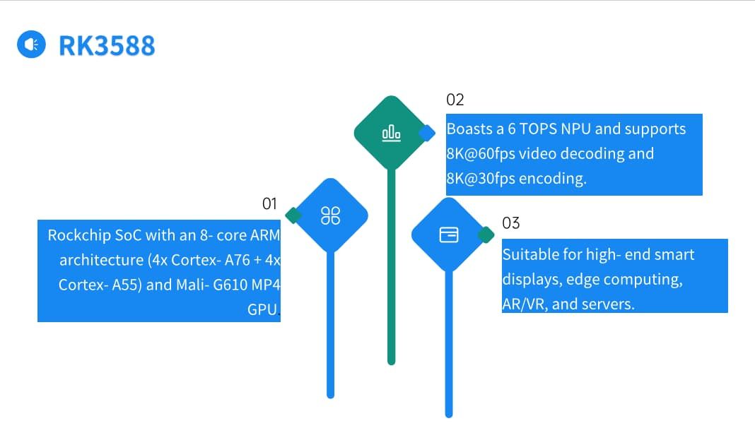
As a new generation of high-performance AI vision processing chip, RK3588's built-in RKNPU Gen 4th architecture provides critical edge computing capabilities for robots. This NPU adopts a new multi-core self-developed architecture, including 3 independent NPU cores, and supports single-core, dual-core and triple-core joint working modes. In terms of computing power performance, RK3588 can provide up to 6.0TOPs of INT8 computing power. Compared with the previous generation RK356X, the single-core performance is significantly improved. Under the Mobilenet_v1 model, the performance is improved by up to 2.11 times. This computing power redundancy is crucial for AI vision system PCB design, which allows local real-time processing of multiple camera inputs and supports 4K@30fps high-definition video encoding and decoding, thereby reducing cloud dependency latency.
In the design of RK3588 core board, the power consumption fluctuation of the NPU under high load needs to be fully considered. According to the chip specifications, the main frequency can reach up to 2.4GHz, which places strict requirements on the stacking structure and impedance control of the PCB. The design needs to ensure the propagation delay consistency of high-speed signal lines, and the delay difference within a differential pair usually needs to be controlled within 5ps to avoid timing violations. At the same time, for the rk3588 pvt sensors interface, snake-shaped wiring needs to be used to compensate for the length to ensure the synchronization of sensor data sampling.
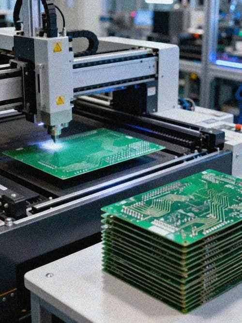
High-speed PCB stack-up design and signal integrity assurance
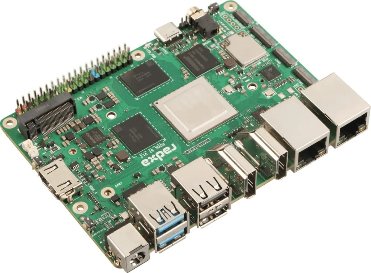
In order to meet the strict requirements of current carrying capacity and signal transmission, the PCB design of the core main control system usually uses high-performance substrates. In the case of an artificial intelligence main control system, S1000H was selected as the base material, which has good electrical properties, mechanical strength and heat resistance. The board thickness is set to 1.6mm, with a 6-layer structure design and a copper thickness of 1oz. This stacking solution has been widely proven in Industrial control PCB design and can effectively balance cost and performance.
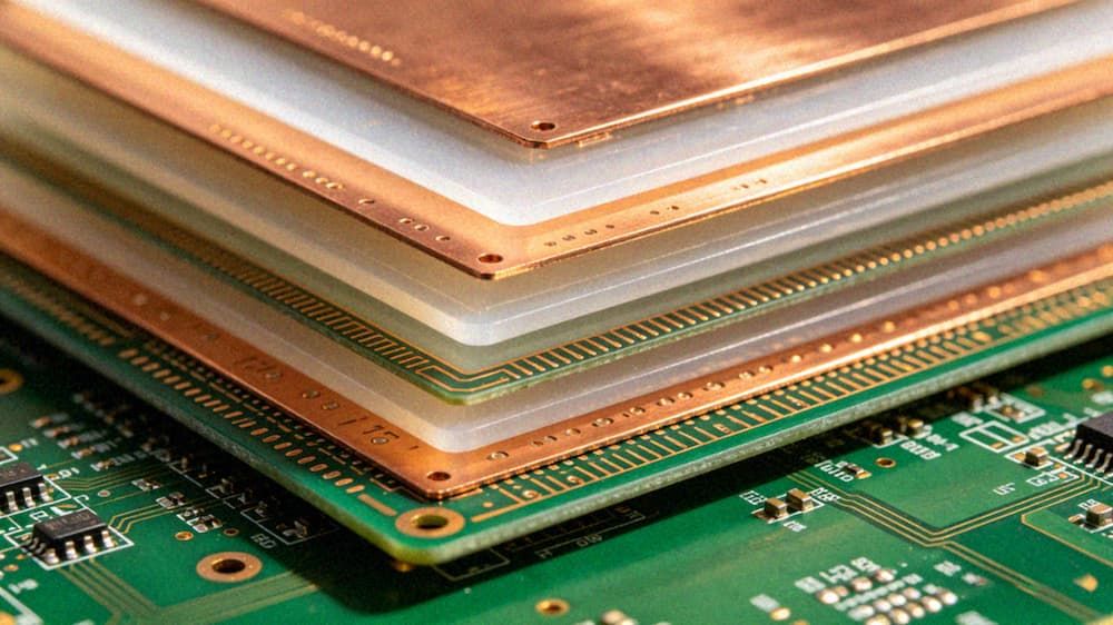
In HDI PCB process applications, the settings of line width and line spacing need to ensure sufficient electrical isolation. Although the specific values depend on the project, in areas with high isolation requirements, line width and line spacing need to be rigorously simulated and verified. For high-speed signal boards, insertion loss is a key indicator. Simulation comparison shows that optimizing the dielectric thickness and copper foil roughness can significantly improve high-frequency performance. By optimizing the stackup, insertion loss can meet the <-15dB specification at 28GHz. In addition, the PDN target impedance needs to be designed to be <20mΩ (from DC to 100MHz) to suppress synchronous switching noise (SSN) and ensure power supply stability of AI computing PCB design.
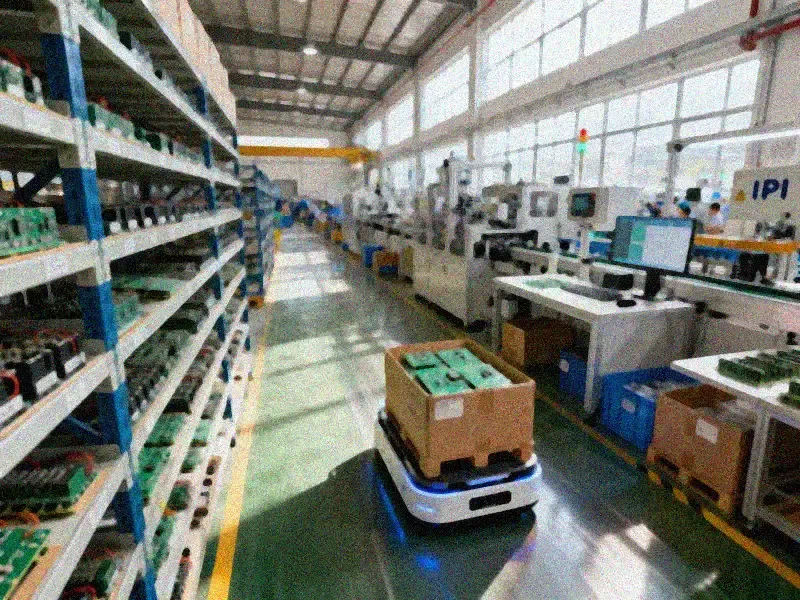
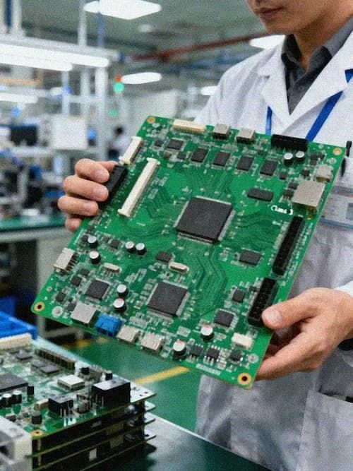
Multi-module system integration and power management strategy
The control system of a humanoid robot is not a single motherboard, but a complex network composed of multiple functional modules. Industrial control system PCB manufacturers usually provide a complete solution including control board, power board, communication board and driver board.
- Control board: As the "brain" of the robot, the head and chest control boards often use the STM32H723VGT6 chip solution. This MCU uses a three-power domain architecture and can develop flexible low-power solutions to realize data transmission and instruction sending.
- Power board: Providing stable power supply for each module is the basis for reliable operation of the system. The control power board uses TI and Jinsheng DC-DC power modules. Through multi-layer circuit board production technology, the circuit layout is precise and can efficiently integrate power supply and control functions.
- Drive Board: The joint drive board uses a specialized motor driver chip MagnTek-MT6835GT, which provides sufficient current and voltage to drive motors of different types and powers, and has overcurrent protection, overheating protection and other functions.
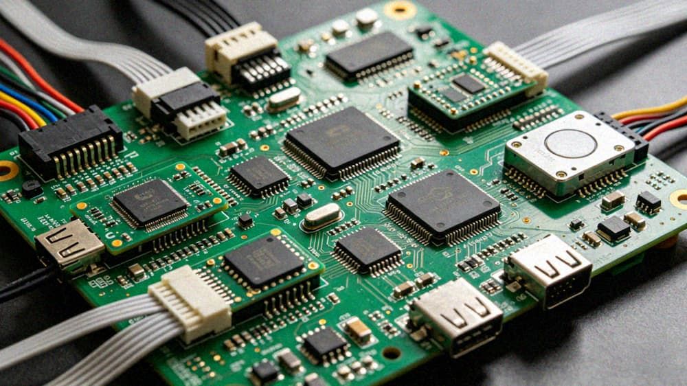
In Industrial Control PCB Solutions, the communication board integrates multi-protocol communication modules such as Wi-Fi, Bluetooth, and Ethernet through PCBA to achieve seamless interconnection between devices. For example, the 5G gateway integrated controller developed based on RK3588 can access the 5G network through 5G NR, while allowing a variety of peripheral devices to access through wired LAN, achieving lightweight AI deployment.
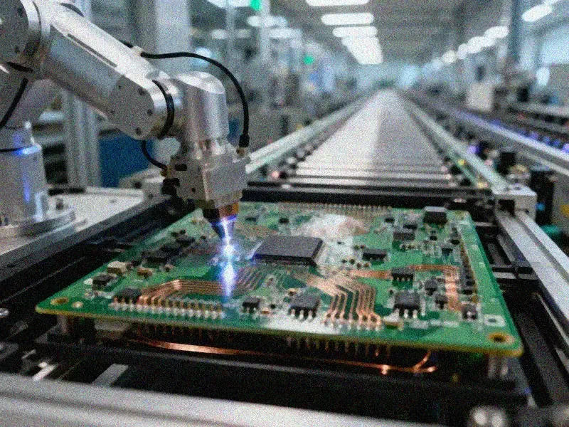
Quality control and verification system for mass production implementation
From PCB Prototype to mass production, the quality control system is the key to ensuring product consistency. In the product matrix of the artificial intelligence industry, the high-reliability nitrogen reflow soldering process is widely used, and the soldering meets the IPC-A-610G III standard. This means that the solder joint reliability has reached the highest level in the industrial control field and can withstand vibration and temperature cycles during robot movement.
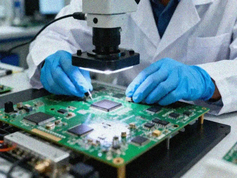
In addition, 100% FCT testing (functional testing) is incorporated into the standard production process, covering the entire chain from design to manufacturing. In a humanoid robot project layout solution, the core board adopts a car-grade design + a composite heat dissipation system, and is equipped with a high-efficiency heat sink to effectively reduce the temperature of the chip during work. This design not only improves temperature resistance, but also enhances vibration resistance and electromagnetic interference resistance. By providing BOM optimization, device procurement and management, and one-stop solution to R&D and production needs, Industrial control system PCB manufacturers can significantly shorten the product launch cycle and ensure supply chain security under the trend of mass production of humanoid robots.
To sum up, the humanoid robot PCB control solution based on RK3588 successfully integrates high-performance computing, multi-modal perception and precise motion control. Through strict SI/PI design, modular system integration and automotive-grade quality control, this solution provides a solid hardware base for future technological life.