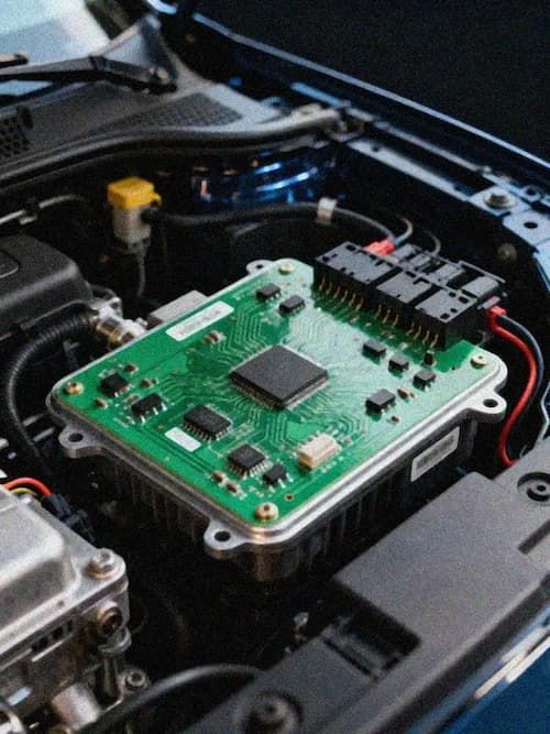
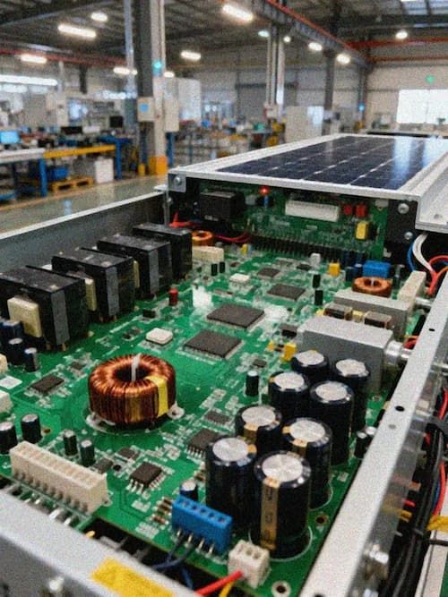
IEC 61850 pulls Ethernet into substations, has communication boards become more complex?
In-station communication in the power industry has undergone an intergenerational switch from serial bus to Ethernet. In traditional solutions, the protection measurement and control devices are interconnected through RS485 or CAN bus, and the communication rate usually does not exceed 1Mbps. The wiring is simple, isolation is easy, and the PCB design threshold is relatively low. The promotion of the IEC 61850 standard has changed this pattern. This standard uses Ethernet as the physical layer and defines two core message mechanisms: GOOSE (General Object-Oriented Substation Event) and SV (Sample Value). GOOSE messages are used for fast message transmission between switching equipment, and the time from event occurrence to message delivery is required to be within 4ms;SV messages are used to merge units to transmit high-precision sampling data to protection devices, with a transmission rate of 4000 frames per second, each frame contains 12-bit or 16-bit sampling values from multiple channels. This leap in communication bandwidth and real-time performance directly drives up the design complexity of PCB.
PCBs that support IEC 61850 communications require integrated Ethernet PHY chips and RJ45 or optical transceiver interfaces. Differential traces of 100Mbps Ethernet PHY require strict impedance control, usually requiring 100Ω differential impedance, and trace length matching error is controlled within ±5 mils to reduce signal reflection and jitter. Some high-end applications have begun to adopt Gigabit Ethernet PHY. Differential traces require higher impedance control accuracy. Stacked design requires a special high-speed signal layer to form a complete return path with the power layer and ground plane. The layout location of the PHY chip directly affects the signal quality-it should be as close to the connector as possible to shorten the differential trace length, and at the same time stay away from high-noise areas such as switching power supplies. Kingbrother has accumulated rich engineering experience in high-speed communication PCB design and can provide full-process support from stack design, impedance simulation to EMC optimization, helping power equipment manufacturers shorten the development cycle of IEC61850 communication boards.
The electromagnetic environment of power secondary equipment itself is relatively harsh, and the IEC 61850 communication board must also meet the strict requirements of the IEC 61000-4 series standards. Ethernet differential traces generate radiated interference during high-speed switching, and external surges and fast transients may also be coupled to the PHY chip through the RJ45 interface. PCB design requires a TVS diode and common mode choke at the Ethernet interface, decoupling capacitors need to be placed nearby on the power pins of the PHY chip, and the ground plane needs to be intact to provide a low-impedance return path. These EMC design measures are rarely involved in traditional RS485 communication boards and are a new difficulty in the design of IEC 61850 communication boards.
Combining units, protection devices and smart terminals, the PCBs of the three devices have their own focus
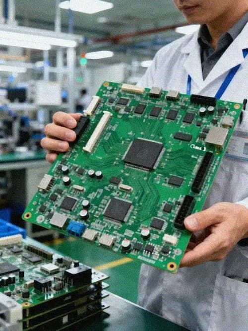
The merge unit is a key equipment in a digital substation and is responsible for converting the analog signals of traditional electromagnetic transformers or electronic transformers into IEC61850 SV sampling value messages. MU's PCB needs to handle both analog sampling and digital communication functional modules. The analog sampling part requires a high-precision ADC circuit, which usually uses a 16-bit or higher resolution ADC chip. The reference voltage trace needs to be as short as possible and away from the noise source. The analog ground and digital ground of the sample-and-hold circuit need to be connected at a single point to avoid Ground loop interference. The digital communication part needs to integrate an FPGA or communication processor, which is responsible for framing and Ethernet transmission of SV messages. There are both high-precision analog circuits and high-speed digital circuits on an MU card. The zoning layout and ground plane design of the PCB are key challenges-reasonable ground plane division between the analog area and the digital area needs to be used to isolate interference, while ensuring that the signal is transmitted across regions. The return path is continuous.
The protection measurement and control device is responsible for fault detection, protection and control logic, and is the core equipment of the substation. The PCB of such devices is usually a 6 to 12-layer board that integrates a DSP or FPGA processor, multiple ADC sampling channels, an Ethernet communication interface, a digital IO interface, and a relay driver circuit. Protection devices have extremely high requirements for real-time performance. The response time from fault occurrence to protection action is usually required to be within 20 to 40ms, and the signal transmission delay on the PCB must be accurately controllable. In addition, protective devices need to meet the IEC 60255 series of standards, which clearly stipulates the insulation fit, creepage distance and electrical clearance of PCBs. Crosstalk suppression between multiple ADC sampling channels is also a design difficulty, which needs to be achieved through reasonable ground plane division and shielded traces.
Intelligent terminals are installed near primary equipment (circuit breakers, isolating switches) and are responsible for status collection of switching equipment and execution of control instructions. Since the installation location is close to high-voltage primary equipment, electromagnetic interference is stronger, and the EMC design margin of the PCB needs to be higher than that of the protective measurement and control device. The PCB design of smart terminals also faces strict environmental adaptability requirements-the working temperature range usually requires-40 ° C to +85 ° C, and needs to withstand the high temperature and high humidity environment inside the outdoor box. The board integrates optoelectronic isolation digital IO interface, Ethernet communication interface and local operation loop. The layout of optoelectronic isolation devices and the spacing design of isolation areas are the key to ensuring reliability.
##Combining units, protection devices and smart terminals, the PCBs of the three devices have their own focus The merge unit is a key equipment in a digital substation and is responsible for converting the analog signals of traditional electromagnetic transformers or electronic transformers into IEC61850 SV sampling value messages. MU's PCB needs to handle both analog sampling and digital communication functional modules. The analog sampling part requires a high-precision ADC circuit, which usually uses a 16-bit or higher resolution ADC chip. The reference voltage trace needs to be as short as possible and away from the noise source. The analog ground and digital ground of the sample-and-hold circuit need to be connected at a single point to avoid Ground loop interference. The digital communication part needs to integrate an FPGA or communication processor, which is responsible for framing and Ethernet transmission of SV messages. There are both high-precision analog circuits and high-speed digital circuits on an MU card. The zoning layout and ground plane design of the PCB are key challenges-reasonable ground plane division between the analog area and the digital area needs to be used to isolate interference, while ensuring that the signal is transmitted across regions. The return path is continuous. The protection measurement and control device is responsible for fault detection, protection and control logic, and is the core equipment of the substation. The PCB of such devices is usually a 6 to 12-layer board that integrates a DSP or FPGA processor, multiple ADC sampling channels, an Ethernet communication interface, a digital IO interface, and a relay driver circuit. Protection devices have extremely high requirements for real-time performance. The response time from fault occurrence to protection action is usually required to be within 20 to 40ms, and the signal transmission delay on the PCB must be accurately controllable. In addition, protective devices need to meet the IEC 60255 series of standards, which clearly stipulates the insulation fit, creepage distance and electrical clearance of PCBs. Crosstalk suppression between multiple ADC sampling channels is also a design difficulty, which needs to be achieved through reasonable ground plane division and shielded traces. Intelligent terminals are installed near primary equipment (circuit breakers, isolating switches) and are responsible for status collection of switching equipment and execution of control instructions. Since the installation location is close to high-voltage primary equipment, electromagnetic interference is stronger, and the EMC design margin of the PCB needs to be higher than that of the protective measurement and control device. The PCB design of smart terminals also faces strict environmental adaptability requirements-the working temperature range usually requires-40 ° C to +85 ° C, and needs to withstand the high temperature and high humidity environment inside the outdoor box. The board integrates optoelectronic isolation digital IO interface, Ethernet communication interface and local operation loop. The layout of optoelectronic isolation devices and the spacing design of isolation areas are the key to ensuring reliability.
IEC 60255, IEC 61000-4 and wide temperature environment, the industry threshold created by the superposition of three standards
IEC 60255 is a basic standard series for relay protection devices, covering many aspects such as performance requirements, environmental conditions and insulation coordination of protection devices. The ones that have the greatest direct impact on PCB design are IEC 60255-27 (Electromagnetic Compatibility Requirements for Measuring Relays and Protection Devices) and IEC 60255-5 (Insulation Fit, Air Clearance and Creepage Distances). In terms of insulation coordination, PCBs of power secondary equipment need to meet certain creepage distance and clearance requirements-the safe spacing between traces of different voltage levels and between strong and weak electrical isolation areas needs to be determined through calculation. The surface of the PCB is usually required. Conformal coating is used to enhance insulation performance. These requirements are rarely covered in ordinary industrial control PCBs and are a special threshold for PCBs in the power industry.
The IEC 61000-4 series standards stipulate electromagnetic compatibility test methods for electrical and electronic equipment. The test items that power secondary equipment needs to pass include: IEC 61000-4-2 Electrostatic discharge (ESD, ±4kV contact discharge/± 8kV air discharge), IEC 61000-4-3 radiated immunity (10V/m, 80MHz-1GHz), IEC 61000-4-4 electrical fast transient pulse train (EFT, ±4kV), IEC 61000-4-5 surge immunity (±4kV line/±4kV line ground), IEC 61000-4-6 conducted immunity (10V, 150kHz-80MHz). These test projects put forward comprehensive EMC requirements for PCB design-ESD protection requires TVS diodes at the interface, EFT and surge protection require varistors and gas discharge tubes at the power inlet, and radiation and conduction immunity need to be achieved through a reasonable ground plane design, decoupling capacitor layout and shielding measures. PCB designers need to find a balance between these EMC measures and signal integrity.
The working environment of secondary power equipment spans a large span. From outdoor distribution stations with high temperatures and humidity in the south to severe cold transmission lines in the north, PCBs need to withstand temperature cycles of-40 ° C to +85 ° C (-45 ° C to +90 ° C in some scenarios), as well as environmental stresses such as high humidity, salt fog, and dust. Plate selection is the basis for environmental adaptability-the Tg value of ordinary FR-4 plates is usually between 130 and 140°C. Mechanical strength and size stability decrease in high temperature environments, making it not suitable for long-term reliability requirements of power secondary equipment. High Tg plates (Tg above 170°C) maintain better mechanical properties and lower CTE (coefficient of thermal expansion) at high temperatures and are the mainstream choice for PCBs in the power industry. In addition, the surface treatment process of PCB also needs to consider environmental factors-HASL (tin spray) may have tin whiskers problems in high temperature and high humidity environments, and ENIG (chemical nickel gold) or OSP (organic solder retaining film) is used in power equipment. More widely. Kingbrother has accumulated rich experience in processing high Tg plates in PCB manufacturing in the power industry, and can recommend suitable plate systems and surface treatment processes according to specific application scenarios.
Digital grid investment has entered the stage of scale, PCB supplier opportunities lie in capacity matching
The digital upgrade of smart grids is moving from pilot to large-scale deployment. The digital substation construction plan of the State Grid and China Southern Power Grid has entered the stage of comprehensive promotion, and the bidding volume of distribution network automation terminals continues to grow. Every digital substation, every distribution network automation terminal, are inseparable from PCB-communication board, sampling board, control board, power board. This market is different from the rapid iteration of consumer electronics. The life cycle of power equipment is usually 10 to 15 years. Once it enters the supply chain, suppliers 'orders are highly stable.
The threshold for PCBs in the power industry is not low. The high-speed Ethernet design capabilities of the IEC 61850 communication board, the compliance experience of the IEC 60255 and IEC 61000-4 standard systems, the accumulation of processing technologies for high-Tg plates, and reliability verification in wide-temperature environments-these capabilities constitute a substantial barrier to PCB supply in the power industry. The market opportunities brought by the digital upgrade of smart grids are not equally distributed, and suppliers with the above combination of capabilities will gain greater market share and higher customer stickiness.