Overview
PCB assembly standards are the foundational technical specifications that guarantee consistent, high-quality printed circuit board assembly (PCBA) production across all project scales. Ambiguity in assembly requirements often leads to misplaced components, soldering defects, low yield, and even premature product failure, resulting in significant cost overruns and delayed time-to-market for electronic product teams. Standardized PCB assembly guidelines cover every stage of the assembly process, from PCB dimensional limits, component packaging compatibility, soldering process parameters to special process adaptability, ensuring design intent is accurately translated into functional finished products while meeting the reliability requirements of different industry verticals. These standards apply to both conventional mass production and specialized low-volume high-mix assembly projects, providing a unified technical reference for design teams, manufacturing teams, and quality control teams.
Technical Capabilities
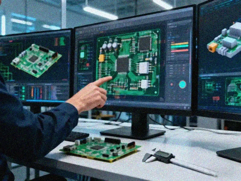
Modern PCB assembly standards support a wide range of process capabilities to adapt to evolving electronic product design demands, covering both conventional and specialized assembly requirements:
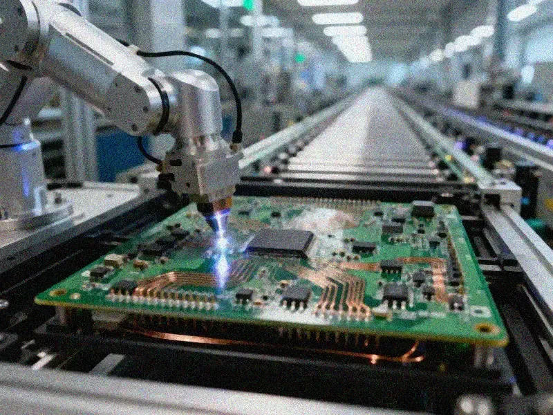
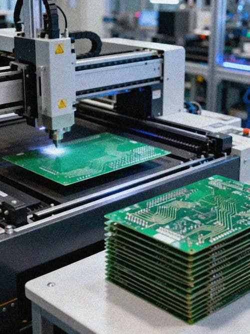
- SMT (Surface Mount Technology) Process Specifications
- Dimensional limits: Conventional PCB sizes meet L≥50mm, W≥50mm requirements, with support for smaller unconventional PCB sizes within semi-automatic printing equipment limits, up to maximum sizes of L≤600mm, W≤450mm. The distance between top/bottom surface components, Mark points, and the board edge is required to be ≥3mm to ensure accurate placement and soldering.
- Component compatibility: Standard component thickness ranges from 0.5mm to 3mm, with support for components thinner than 0.5mm or thicker than 3mm for specialized designs. Minimum component packaging supports 0201 (0.6mm0.3mm) as standard, with optional support for ultra-small 01005 (0.3mm0.2mm) packages for high-density designs. Double-sided process device height is limited to ≤25mm, with standard SMD size limits of ≤200mm*125mm and support for larger SMD components on request.
- Fine pitch capability: Standard minimum placement accuracy reaches 0.5 pitch, with support for finer pitch requirements for high-pin-count components. For QFP, SOP, SOJ and other multi-pin packages, standard minimum pin spacing is 0.35mm, with support for 0.3mm to 0.35mm pin spacing for specialized designs. For CSP and BGA packages, standard minimum ball spacing is 0.35mm, with support for 0.3mm to 0.35mm ball spacing for high-density interconnection requirements.
- DIP (Dual In-line Package) Wave Soldering Specifications
- Conventional PCB size requirements are L≥50mm, W≥50mm, with support for smaller PCBs under L=50mm if two conditions are met: bottom surface elements are smaller than 5mm, and the distance between plug-in component pins and SMT parts on the bottom surface is greater than the SMT part thickness + 2.0mm. Maximum PCB size for wave soldering is L≤500mm, W≤400mm.
- Component thickness for through-hole assembly supports up to 15mm as standard, with support for thicker components on request.
- Special Process Support Standard PCB assembly standards also cover compatibility with advanced PCB fabrication and assembly processes, including blind and buried vias, metal core PCBs, rigid-flex PCBs, embedded copper structures, high-frequency hybrid material boards, long and short gold connectors, back drilling, depth control drilling, via in pad, half holes, countersinks, step slots, stack vias, laser cutting, epoxy fill, mixed surface finishes, embedded components, and carbon ink printing, adapting to the most demanding specialized product design requirements.
Quality Standards
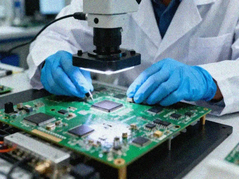
All PCB assembly processes follow internationally recognized quality control specifications to ensure finished product reliability:
- Compliance with International Standards: Assembly processes align with IPC-A-610 (acceptability of electronic assemblies) and IPC-J-STD-001 (requirements for soldered electrical and electronic assemblies), with three quality classes available for different application scenarios: Class 1 for general consumer electronics, Class 2 for industrial and commercial electronics, and Class 3 for high-reliability applications such as medical, aerospace, and automotive safety components.
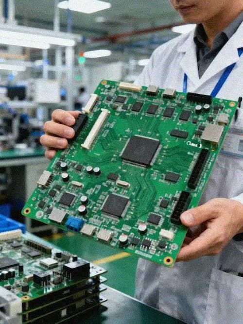
- Full-Process Inspection Protocols: Standard inspection processes include post-printing solder paste inspection (SPI), automated optical inspection (AOI) after placement and reflow, X-ray non-destructive inspection for BGA/CSP and hidden solder joints, in-circuit testing (ICT) for electrical connectivity, and functional testing (FCT) as required by project specifications.
- Reliability Testing Requirements: For high-reliability applications, additional testing protocols are defined in assembly standards, including thermal cycling testing, humidity and heat resistance testing, vibration testing, and salt spray testing to ensure products can operate stably in harsh environmental conditions.
Applications
Standardized PCB assembly standards adapt to the requirements of a wide range of electronic product verticals:
- Consumer Electronics: Meet the high-density assembly requirements of smartphones, wearable devices, smart home products, and consumer entertainment equipment, supporting ultra-small component packaging and low-cost mass production requirements.
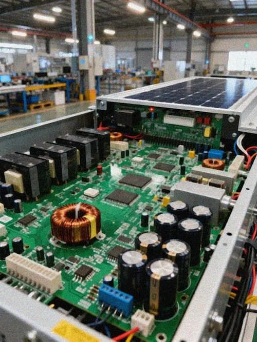
- **Industrial Control Equipment: Comply with long-term operational reliability requirements for industrial controllers, sensor modules, power supply units, and automation equipment, adapting to wide temperature, high vibration, and dust-prone operating environments.
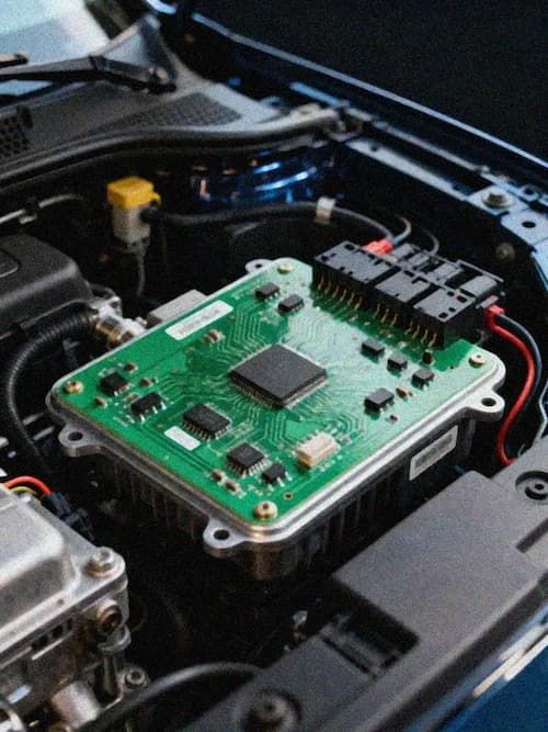
- Automotive Electronics: Meet IATF 16949 aligned assembly requirements for autonomous driving domain controllers, smart cockpit units, in-vehicle sensor systems, and power management modules, ensuring zero defects for safety-critical components.
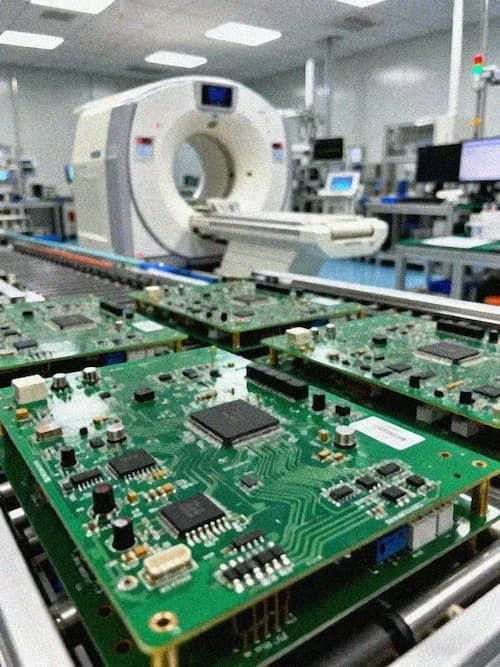
- **Medical Devices: Comply with ISO 13485 aligned quality requirements for diagnostic equipment, patient monitoring devices, implantable medical electronics, and medical imaging systems, meeting strict biocompatibility and long-term reliability standards.
- **Telecommunications Infrastructure: Support high-frequency, high-speed assembly requirements for 5G base stations, communication routers, optical module units, and data center equipment, ensuring high-speed signal transmission integrity.
- **High-Performance Computing: Adapt to high-density interconnection requirements for AI computing boards, server motherboards, and edge computing nodes, supporting large-size PCBs and high-pin-count BGA/CSP component assembly.
Key Advantages
Adopting standardized PCB assembly standards delivers multiple tangible benefits for electronic product development and production teams:
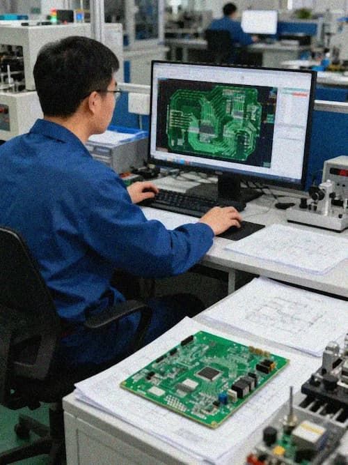
- Reduced Production Risk: Clear, unified technical specifications eliminate communication ambiguity between design and manufacturing teams, reducing the risk of design for manufacturing (DFM) errors, rework, and scrap, shortening product development cycles by 20% to 30% on average.
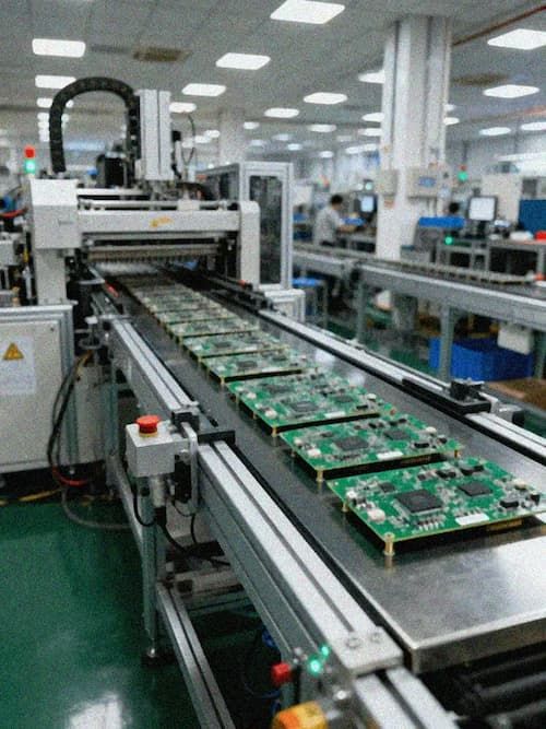
- Consistent Batch Quality: Standardized process parameters and inspection protocols ensure consistent assembly quality across production batches, with defect rates controlled to below 50 DPMO for mass production, reducing after-sales maintenance costs and product recall risks.
- **Cross-Industry Compatibility: Predefined quality classes and process capabilities allow teams to easily adjust assembly requirements to match the regulatory and performance demands of different industry verticals, without needing to develop custom process guidelines from scratch.
- Cost Optimization: Standardized guidelines help teams balance performance and manufacturing cost, avoiding unnecessary over-design that increases production costs, while also preventing under-design that leads to reliability issues, reducing overall product total cost of ownership by 15% to 25% on average.
Contact Information
If you have questions about PCB assembly standard applicability, need to verify the assembly compatibility of your PCB design, or require customized process guidelines for specialized product requirements, you can contact our technical support team at any time. We provide free DFM reviews, process feasibility evaluations, and targeted technical consultation services to help you deliver high-quality, cost-effective PCBA products on schedule.