Signal integrity proposition in the 224G era
Data center switch port speeds have entered the era of 224Gbps, and the fundamental frequency under PAM4 modulation has climbed to 56GHz. Near this frequency, the insertion loss of PCB traces becomes the primary bottleneck in channel design. The superimposed effect of factors such as material loss, copper foil roughness, and residual via piles is significantly amplified in high-speed scenarios, and low-loss materials are transformed from optional configurations to design requirements. The industry's attention to the loss tangent (Df) parameter has long been focused on the value on the frequency axis, and discussions on its drift characteristics with temperature have been relatively limited. In fact, in systems such as 224G with extremely tight loss budgets, the temperature drift behavior of Df is becoming a hidden variable affecting signal integrity, and its influence is large enough to turn critical designs from pass to failure. This paper will start from the temperature drift characteristics of Df parameters, combined with the stack design and manufacturing process, and analyze the application points of M9-level low-loss materials in 224G high-speed PCB.
The 224G PAM4 transmits 2 bits of information per symbol, and the Nyquist frequency reaches 56GHz. At this frequency point, the dielectric loss and conductor loss of the substrate material increase rapidly simultaneously, and the total channel loss budget is very tight. In high frequency bands, the contribution of material Df to total loss shows a nonlinear amplification trend, and the influence of copper foil surface roughness cannot be ignored. The three-level decision threshold of the PAM4 signal places high requirements on the signal-to-noise ratio, and any additional channel loss will directly translate into eye closure and an increase in bit error rate. For every 0.001 decrease in the material's Df value, considerable benefits can be brought to the 224G channel margin at typical trace lengths. Taking the 16-inch trace as an example, the Df dropped from 0.002 to 0.0015, and the loss improvement is enough to allow additional margin for channel design in critical states. After entering the 224G era, the balanced compensation space has been greatly reduced, and the weight of material selection has continued to rise throughout the design process. At the same time, the stability of the Dk (dielectric constant) parameter has also attracted more attention, and its fluctuations will directly affect the precise control of the characteristic impedance.
Df/Dk Temperature Drift Characteristics and Material Selection
The Df parameter of M9-level low-loss materials is usually in the range of 0.0012 to 0.0015 at room temperature of 25°C, which is further lower than the 0.0015 to 0.002 for M8N-level. This numerical advantage is directly reflected in lower dielectric loss near the 56GHz fundamental frequency, providing a more generous loss budget starting point for the 224G channel. What deserves more attention is the temperature drift behavior of Df parameters. Measured data show that when the M9 material heats up from 25°C to 85°C, the Df value may increase by 15% to 25%, and in extreme cases the temperature drift amplitude can reach more than 0.0003. This kind of drift cannot be ignored in a data center environment operating at a wide temperature. In summer, the temperature of the heat channel in the computer room is close to 40°C, and local hot spots may exceed 60°C. The accumulation of temperature rise in Df will directly erode the already tight loss budget. If only the room temperature Df value is used as the simulation input during the design stage, the actual loss during high temperature operation may exceed expectations by 0.5dB to 1.2dB. This increase is enough to cause insufficient eye margin in a 224G system with tight margin. At the same time, the drift coefficient of the Dk parameter with temperature is about minus 50 to 80ppm per degree Celsius, and its fluctuations will directly affect the precise control of characteristic impedance. In 224G differential channels, impedance deviation tolerances have been tightened to extremely high levels, and impedance deviations caused by temperature drift in Dk may be amplified as a signal integrity risk when the system is operating at high temperatures.
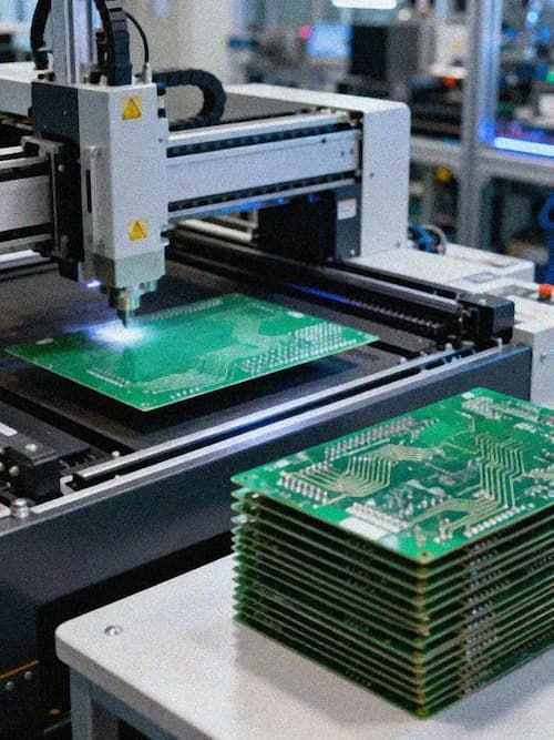
Residual via piles will form a resonant cavity at a specific frequency, causing impedance discontinuities and energy reflections. The spectrum coverage of the 224G signal is wider, and the threshold for the tolerable length of the residual pile has shrunk significantly compared with the 112G era. The back-drilling process can improve this problem, but the depth accuracy is limited at the manufacturing level. Excessive pursuit of minimizing residual piles may bring interlayer alignment risks. Although blind hole and buried hole technology can completely eliminate residual piles, it increases the number of lamination times and process complexity. In high-level multilayer boards of 16 to 32 layers, a comprehensive evaluation of the balance between cost and performance is needed. The impedance deviation tolerance of the differential channel has been tightened to a very high level in the 224G design. The manufacturing end achieves an impedance control accuracy of ±5%, which requires the entire process from material cutting, inner layer etching to outer layer lamination. Control. Signal reflection caused by impedance deviation will be directly reflected in a reduction in eye opening. Simulations show that an impedance deviation of ±10% may cause eye height to drop by more than 20%, while a control accuracy of ±5% can compress the impact to an acceptable range. Parameter deviations caused by long-term environmental factors such as temperature drift and humidity aging need to be included in the calculation of design margins in 224G products.
The intergenerational evolution of high-speed PCB substrates follows the law of signal rate driving. The Df value of M6 material is in the range of 0.004 to 0.006, which is suitable for speeds from 25G to 56G; M7N is advanced to around 0.003, becoming a common option for 112G; M8N and higher materials reduce the Df to around 0.0015 or even lower, providing a material basis for 224G. The Dk values of different grades of materials also differ, which directly affects the design calculation of characteristic impedance and trace delay. In high-rise multilayer laminate designs of 16 to 32 layers, material levels need to be optimized in conjunction with inter-layer distance, copper foil type and glass cloth specifications to achieve a balance between loss and manufacturability. The type and resin content of glass cloth have a significant impact on the uniformity of Dk. Low Dk glass cloth such as NE glass can further reduce the dielectric constant and improve its frequency stability. TU933 + high-speed plate has accumulated rich application experience in AI computing server motherboards. The Df/Dk parameters of this material remain stable over a wide frequency range and have practical simulation value for accurate impedance control near 56GHz. In the 16-to 32-layer lamination process, the experience of using TU933 + with low-flow PP sheets has been mature, and the interlayer alignment accuracy and dielectric thickness uniformity after lamination can meet the requirements of high-speed channels. Compared with M-series materials, TU933 + has differentiated advantages in terms of cost structure and supply chain maturity, forming a complementary pattern in mid-to-high-end high-speed PCB selection.
Process boundary from PCB to Substrate
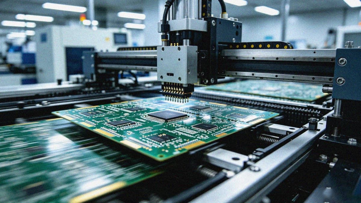
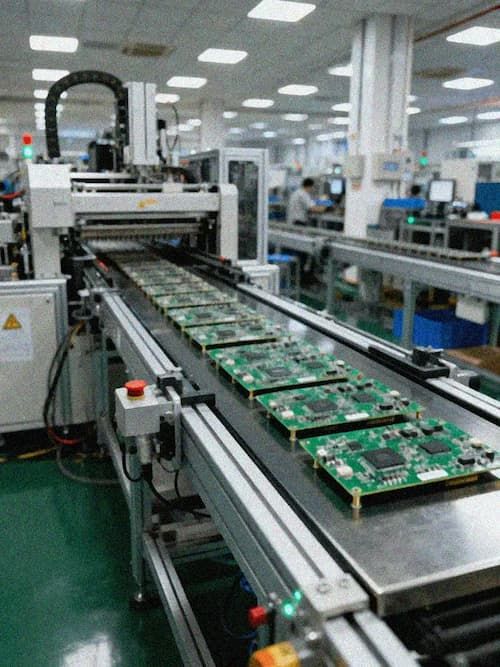
The manufacturing accuracy of IC Substrate directly determines the signal integrity of high-speed chips after packaging. The current Substrate-level template line width and line spacing accuracy reaches 25/25um, and mass production is stable at 30/30um, which is enough to support the dense arrangement of differential signal lines in 224G chip packages. Packaging substrate manufacturing involves precision processes such as blind hole plating filling, surface treatment and multi-layer alignment. The accumulation of errors in each process will ultimately be reflected in the quality of signal transmission. For devices such as GPUs and swap chips that require a large number of high-speed IO connections in a very small space, the improvement of Substrate manufacturing accuracy is a prerequisite for releasing chip performance. The sample verification of 112Gbps signal rate has accumulated rich experience for 224G full-rate verification. The impedance control scheme and back-drilling process parameters that have been mature in the 112G era can be directly migrated and optimized in a targeted manner. The line width and spacing accuracy of the PCB model reaches 2.0/2.0mil, and the mass production maintains 2.5/2.5mil. The number of layers covers 56 layers of the FR-4 system and 30 layers of HDI/arbitrary layer structure. These parameters jointly support the implementation of 224G PCB. The accuracy of back drilling depth directly determines the final length of the residual pile through the hole. In 224G design, the residual pile is usually required to be controlled below a certain threshold to avoid resonance. The multi-back drilling process can achieve more precise management of residual piles in high multilayer boards by removing residual piles at different depths in stages. The depth control accuracy needs to be within ±2 mils to meet the resonance suppression requirements in the 56GHz band.
Temperature drift verification of AI computing server switch board
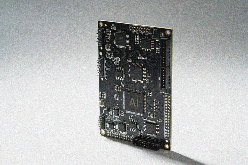
In the high-speed interconnection scenario of AI computing infrastructure, the combined effects of the above materials and process parameters have been intensively verified. An AI computing server switch board adopts a 56-layer FR-4 laminated structure. During the upgrade of the signal rate from 112Gbps to 224Gbps, the material Df parameter switches from 0.003 at the M7N level to 0.0013 at the M9 level. The temperature drift test showed that when the board was operating at full load and the local temperature increased from 25°C to 65°C, the Df value of the M9 material increased from 0.0013 to 0.0016, corresponding to an increase of approximately 0.8dB in channel loss. This increment was reserved and covered in the original design margin, verifying the necessity of pre-modeling the temperature drift characteristics. In the laminate design, the combination of TU933 + and low-flow PP sheets ensures the uniformity of dielectric thickness after 56 layers are laminated. The dielectric thickness deviation of each layer is controlled within ±5%, and the impedance control accuracy is stable within ±5%. The back-drilling process controls the residual pile of the via to below 3 mils, eliminating the risk of resonance near the fundamental frequency of 56GHz, and the channel eye margin still meets the specification requirements under high temperature conditions. This case shows that the signal integrity guarantee of the 224G channel requires the establishment of a collaborative mechanism in three dimensions: material temperature drift characteristics, stack impedance control and manufacturing accuracy. Optimization in a single dimension cannot cover the superposition of variables in actual operation. The temperature drift characteristics of Df parameters change from implicit assumptions to explicit constraints in this case, and its modeling accuracy directly affects the allocation logic of design margins.
Conclusion
As the material Df value is further reduced below 0.001, the constraints of physical limits and cost curves will become more prominent. The temperature drift characteristics of Df parameters have risen from a marginal issue to a core variable that must be included in the design in 224G systems, and its impact is enough to offset the benefits of intergenerational upgrades of materials in some scenarios. The Substrate Like-PCB process is blurring the boundaries between traditional PCBs and IC packaging substrates, providing a physical carrier for the next generation of high-speed interconnects. The large-scale introduction of Anylayer technology in high-speed PCBs is expected to further optimize the flexibility and channel loss performance of inter-layer traces. The expansion of AI computing infrastructure is driving the evolution of GPU switch boards to higher digital levels. The popularity of 800G and 1.6T optical modules has put forward new requirements for PCB channel performance. Suppliers that can establish systematic advantages in the three dimensions of material application, laminate design and precision manufacturing will occupy a more favorable position in the next generation high-speed interconnection market.