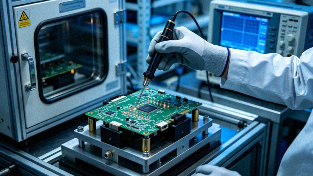
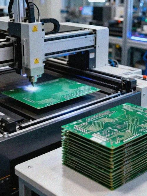
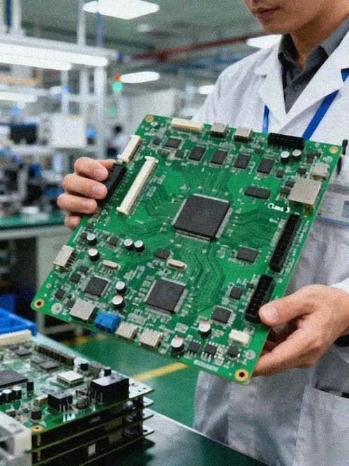
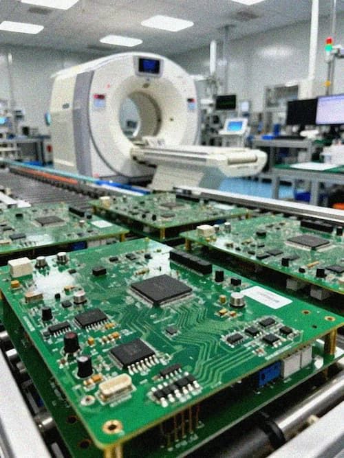
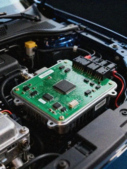
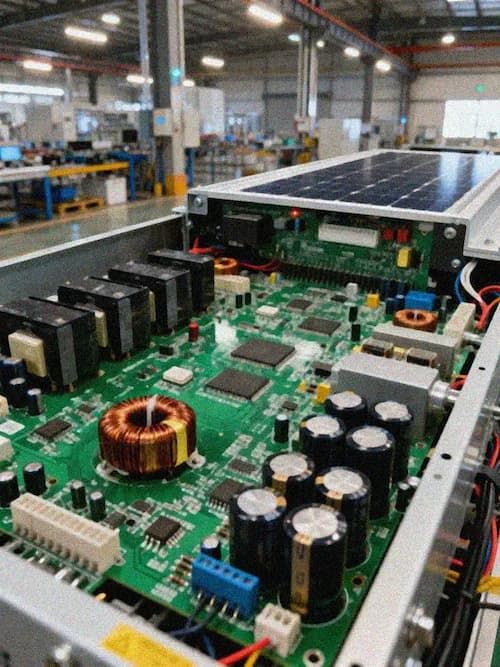
How a robot behaves in 24-hour operation, complex motion, and changing environments ultimately depends on whether its boards hold up over time. A PCB that passes functional testing in the lab can still fail in production or in the field under thermal cycling, vibration, or electromagnetic interference. Boston Dynamics' Spot quadruped has already spent years in industrial inspection and energy-site deployment, where its boards endure vibration, temperature swings, and dust, and that experience shows how field failures are often impossible to reproduce in the lab. The value of reliability testing is to surface those failure modes in advance rather than after delivery.
Design Premises for Reliability Testing
The test plan should derive its severity from the application. Industrial, mobile, and service robots face different temperature, vibration, and lifetime requirements, so test conditions have to match real duty rather than a generic set of parameters. IPC-6012 provides performance and acceptance classes for rigid boards, and Class 2 versus Class 3 acceptance corresponds to different reliability expectations; robots that run for long periods and are hard to service in the field usually need to lean toward the higher class.
Design for testability (DFT) is the precondition for effective testing. Sensible test-point placement, boundary scan, and flying-probe coverage let defects be caught early. If the design leaves no room for test, later electrical testing and fault location both become difficult, and the reliability loop cannot close.
Environmental and Mechanical Testing
Thermal cycling and thermal shock verify durability under temperature change. Cycle profile, cycle count, ramp rate, and failure criteria all need to be explicit, and solder fatigue plus CTE (coefficient of thermal expansion) mismatch are the dominant failure modes when robots combine vibration with heat. Under repeated thermal cycling, solder cracks grow until they cause intermittent opens, a problem that functional testing rarely catches.
Vibration and shock testing address mechanical stress during robot motion. Random vibration, sine sweep, and shock each simulate a different loading state, with conditions referenced to the equipment's actual operating environment. Stiffening, adhesive reinforcement, and structural damping improve vibration reliability, but they should be designed in up front because the cost of adding them after a test failure is considerably higher.
Electrical and EMC Testing
Electrical safety testing covers insulation, leakage current, and dielectric strength, while signal-integrity testing confirms impedance consistency. EMC testing targets the multi-motor-drive scenario, where motor start and stop events can generate conducted and radiated emissions that disturb sensitive circuits, and immunity testing verifies stability under external interference. The IEC 61000 series supplies the systematic framework for electromagnetic compatibility.
Batch Consistency and Field Validation
Batch consistency is where reliability testing lands. IPC-A-610 provides a common acceptance standard for solder, component mounting, and appearance, and AOI, flying-probe, and ICT together stop defects before shipment. Field failure data is just as important, because it carries real operating conditions back into design review and lets the test profile keep evolving, closing the loop from lab to field.
Closing
Robot PCB reliability rests on both test methodology and batch consistency. Thermal cycling, vibration, EMC, and electrical testing are all necessary, and a test system that keeps improving with field data is the one that actually matters. For long-running robot hardware, moving reliability validation ahead of design review costs less than handling field failures after delivery.