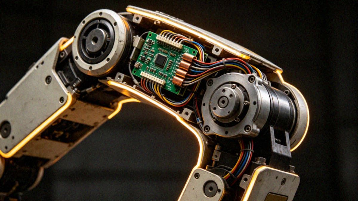
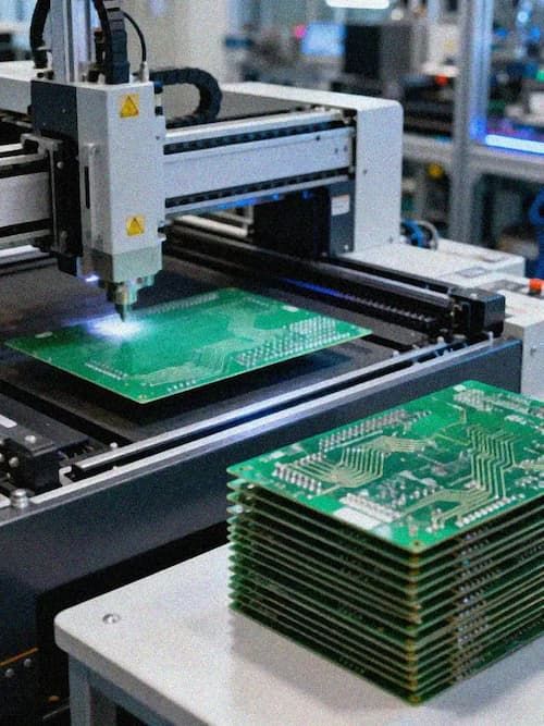
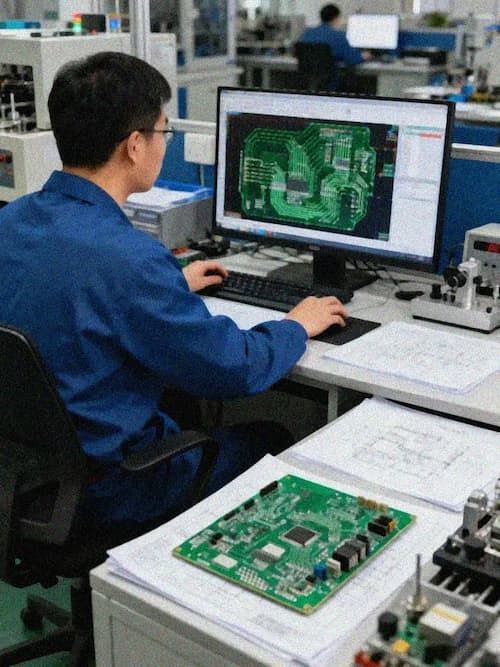
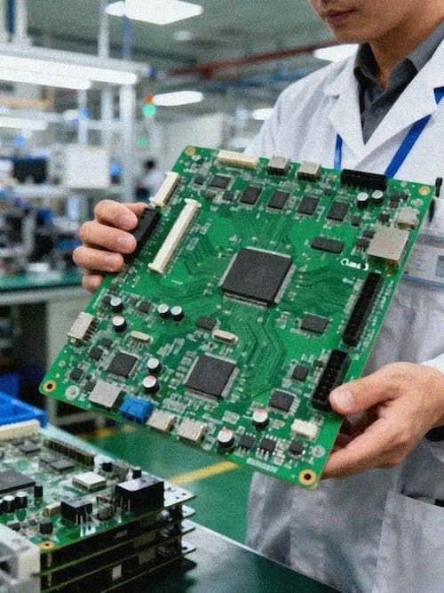
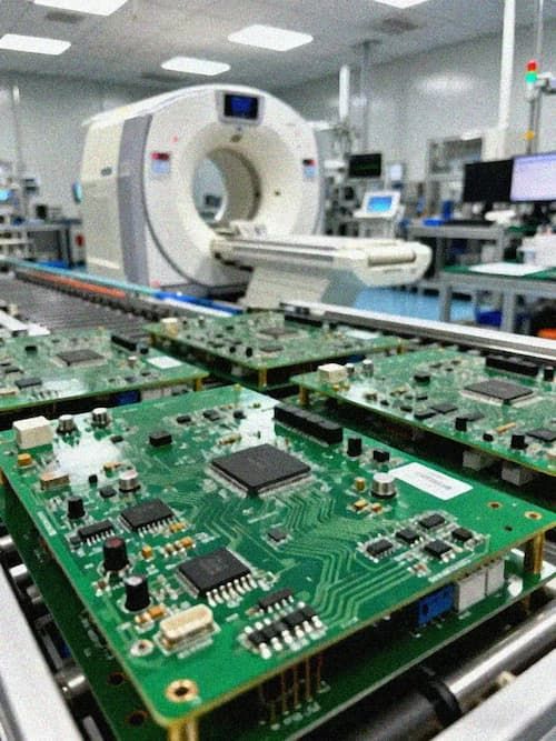
A robot's joint drivers and compute modules both draw heavy current, but power board mistakes usually surface only at the prototype stage. During emergency stops, acceleration, and load changes, supply current on a multi-axis robot swings sharply within a very short window, and any bottleneck in the copper, vias, or connectors turns into temperature rise, voltage drop, or even control instability. Robot power board design is ultimately about finding a producible balance among current handling, thermal behavior, and reliability.
Power System Architecture
A robot power system is usually built as several supply tiers. The battery or external source passes through the BMS (battery management system) and protection circuits before splitting to the joint drivers, sensors, and compute modules. Those loads differ sharply in their voltage-stability and transient-response needs: joint drivers must absorb peak current, while compute modules care more about low ripple and dynamic load capability. Clear supply layering and separate return paths are the precondition for the routing work that follows.
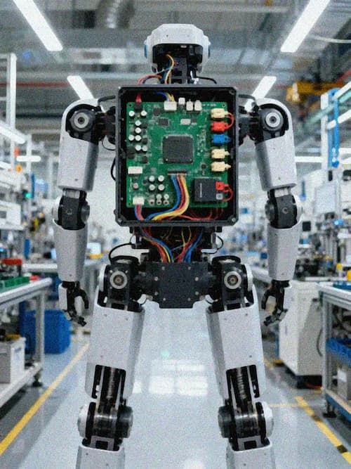
Tesla's Optimus humanoid robot is a useful reference for that high-current requirement. By mid-2026, roughly 200 Optimus units were deployed across the Fremont and Giga Texas plants, and its multi-joint actuation depends on power boards that deliver multiple high-current, fast-response rails. Humanoid robots turn thick copper, parallel vias, and low-impedance PDNs into required engineering elements rather than optional refinements.
High-Current Routing
Current-carrying capacity against trace width and copper weight needs to be calculated rather than estimated. IPC-2152 provides the calculation basis, but real designs have to add a temperature-rise margin. Undersized traces overheat under sustained load and accelerate insulation aging and solder-joint failure, while oversized traces waste board area, raise cost, and squeeze signal routing space.
Copper weight follows current demand. One-ounce copper fits signal layers and low-current power layers, two ounces is the common middle ground for robot power boards, and three ounces or more serves the high-peak drive loops. The tradeoff is that heavier copper makes fine line and space harder to manufacture, so the designer has to settle current demand against process capability before layout is locked. Power planes and vias usually matter more than traces: several parallel vias can substantially reduce the load on any single via, while plane splitting directly shapes return paths and electromagnetic compatibility.
Thermal Management
High current concentrates heat in the copper, vias, and power devices. Thermal pads pull heat from power devices into the copper pour, thermal vias carry heat from inner layers to the heat-spreading surface, and metal-core substrates add more heat diffusion in high-power-density spaces. Thermal design has to be done together with routing, because adding cooling measures after layout is usually far less effective.
Reliability Validation
Robot power boards go through temperature-rise, thermal-cycling, vibration, and EMC validation. Temperature-rise testing confirms whether full-load and peak conditions stay within limits, thermal cycling verifies solder and material durability under temperature change, vibration testing addresses mechanical stress during motion, and EMC testing covers conducted and radiated interference from motor drives. Those results feed back into copper weight, via, and thermal design iteration.
Closing
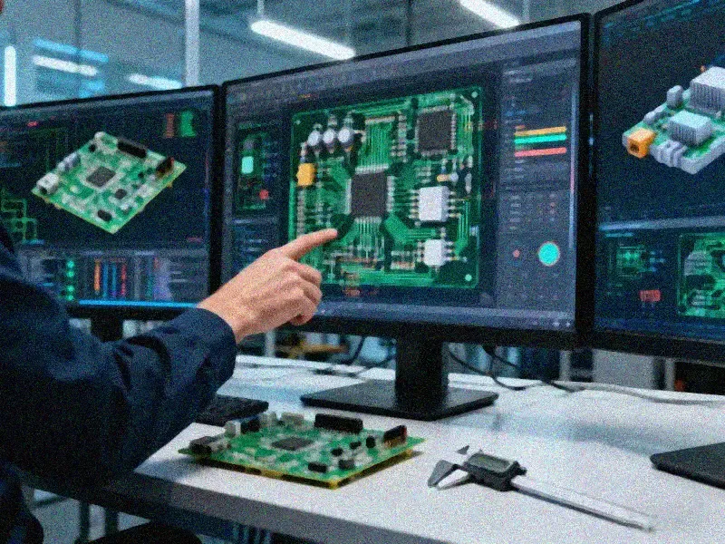
The difficulty of a robot power board lies in solving current handling, thermal, and reliability on the same drawing. Thick copper, metal-core substrates, and rigid-flex are the common process combinations for this class of product, and the real value comes from bringing manufacturing capability into the design early. A routing plan that still exists only as theoretical trace width, when run through a review against real copper and temperature-rise boundaries, tends to expose problems that otherwise appear only at prototype.