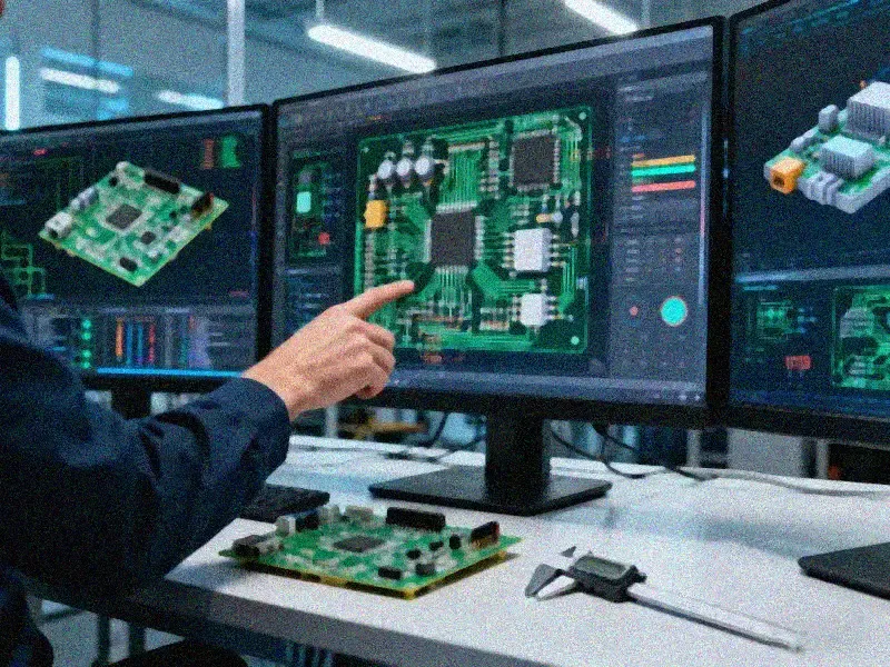
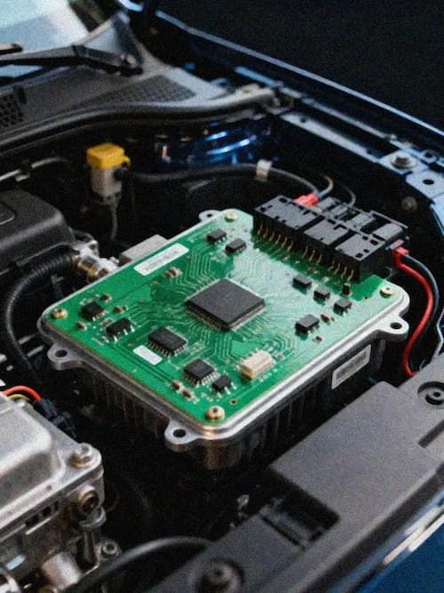
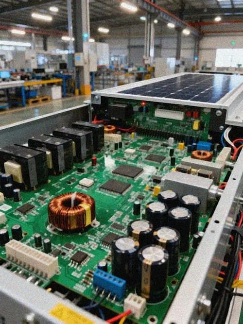
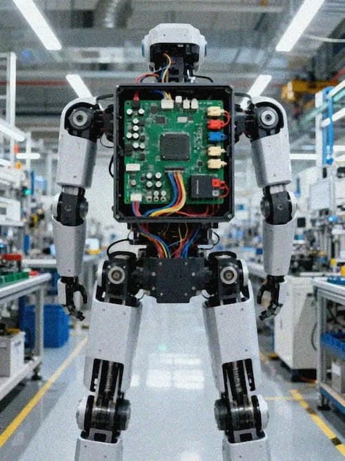
With the rapid development of new energy, industrial automation, and electric vehicles, the PCB design of high-power converters (such as photovoltaic inverters, energy storage converters, and electric vehicle OBCs/DC-DC converters) faces unprecedented challenges. High current, high power density, and high-frequency switching characteristics make current carrying capacity, thermal management, and electromagnetic interference (EMI) key bottlenecks restricting system reliability and efficiency. To ensure stable, safe, and efficient system operation, coordinated optimization is necessary across four dimensions: material selection, structural design, routing strategy, and manufacturing process.
Solutions for High Current Carrying Capacity
The main circuits in high-power converters typically need to carry continuous currents of tens to hundreds of amperes while withstanding transient surges. Traditional 1-ounce (35μm) copper foil is insufficient; high-thickness copper foil and optimized routing strategies are required.
Heavy Copper Design: We recommend using copper foil ranging from 2 oz (70μm) to 6 oz (210μm). For some extreme applications (such as UHVDC transmission and high-power motor drives), ultra-thick copper of ≥10 oz (350μm) can be used. Compared to traditional 1 oz copper foil, resistance can be reduced by more than 60% at the same linewidth, significantly reducing I²R losses and voltage drop.
Wide Conductors and Large Copper Pour: The conductor width of power circuits (such as DC-Link and busbars) should be ≥3mm, and a large copper pour should be used to create a low-impedance current path. For high-current nodes, a copper grid design can be used, combined with dense grounding vias, to effectively reduce temperature rise and thermal stress.
Optimize Layer Stack-up: In multilayer boards, **1-2 layers should be dedicated power layers specifically for transmitting high currents, avoiding mixing with signal layers to minimize current paths and impedance.
Systematic Thermal Management Strategy:
High-power components (such as IGBTs, MOSFETs, and diodes) generate significant heat during high-frequency switching. Failure to dissipate this heat promptly will lead to device failure and shortened lifespan. Thermal management requires addressing materials, structure, and process.
Select High Thermal Conductivity Substrates: Prioritize high TG FR-4 (TG≥170°C), polyimide (PI), or ceramic substrates (such as DBC ceramics or aluminum nitride AlN). These materials maintain mechanical strength and electrical stability at high temperatures. The thermal conductivity of ceramic substrates can reach 10-170 W/m·K, far exceeding that of ordinary FR-4 (0.3 W/m·K).
Integrated Heat Dissipation Structure:
- Aluminum Substrate PCB (MCPCB): Power devices are directly mounted on an aluminum substrate, utilizing its high thermal conductivity to conduct heat to the heatsink, suitable for high power density applications.
- Copper Filling: Copper filling is applied to the inner layer area beneath the power devices, forming a heat conduction path and reducing the thermal resistance from the chip to the PCB surface.
- Thermoelectric Separation Raised Tops: Localized copper-based raised tops are designed in the chip area to physically separate and strengthen the heat dissipation path, improving heat dissipation efficiency.
Optimized Heat Dissipation Path: Heat-generating components are rationally arranged to avoid heat accumulation. By adding ventilation holes (Via Farm) and connecting internal heat dissipation copper layers, heat is efficiently conducted from the heat source to the PCB edge or mounting base. In extreme cases, water cooling or air cooling designs can be combined.
Electromagnetic Interference (EMI) Suppression Technology
High-power switching power supplies are strong EMI sources. Their high-frequency (tens of kHz to MHz) switching operations generate strong conducted and radiated interference, affecting the system itself and peripheral equipment. Suppressing EMI requires a multi-layered, comprehensive protection solution.
Layered isolation and shielding: Employing a four-layer or multi-layer board design (signal/ground/power/shielding layers) to strictly physically isolate high-voltage, high-current power areas from low-voltage, sensitive signal areas. Adding copper foil shielding layers or metal casing shielding in critical areas (such as power input/output terminals) forms a Faraday cage, blocking radiation paths.
Optimized impedance matching and filtering:
- π-type filter circuit (Pi Filter): Integrating a π-type filter (inductor-capacitor-inductor) at the power input and output terminals effectively filters out high-frequency noise.
- Common-mode inductor: Connecting a common-mode inductor in series in the input/output lines suppresses common-mode interference current.
- Precise impedance control: For high-speed control signals (such as PWM, communication signals), employing differential pair wiring and precisely controlling the impedance (e.g., 50Ω or 100Ω) reduces signal reflection and crosstalk.
Grounding and Decoupling Design:
- Establish a low-impedance, low-inductance ground plane to ensure a clear return path for all circuits.
- Place high-frequency decoupling capacitors (such as ceramic capacitors) near the power pins of each power device to absorb switching noise locally.
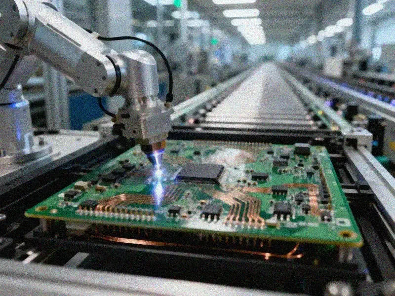
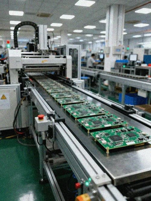
High-Reliability Manufacturing Process Guarantee
The above design intent must ultimately be achieved through a rigorous manufacturing process. It is recommended to use IPC-A-610G Class 3 or IATF 16949 automotive-grade standards for production, combined with the following processes:
Nitrogen Reflow Soldering: Use a nitrogen atmosphere during SMT soldering to reduce oxidation and improve solder joint reliability.
Conformal Coating: Apply conformal coating to the PCBA to enhance corrosion resistance in harsh environments such as humidity, salt spray, and dust.
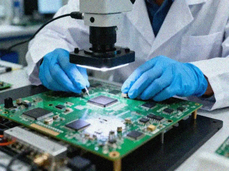
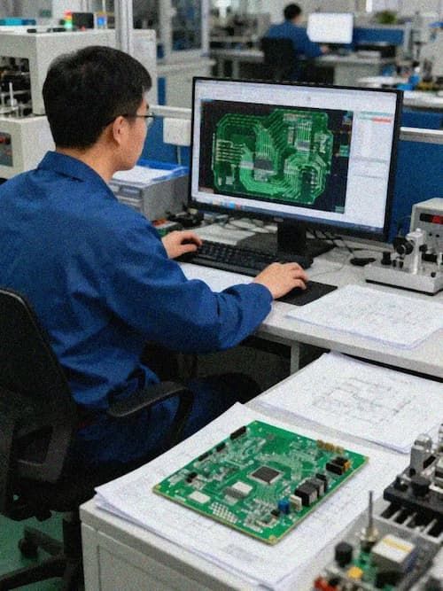
Comprehensive DFM/DFA Analysis: Introducing manufacturability (DFM) and assemblability (DFA) analysis during the design phase helps mitigate design flaws and ensures high production yield.
In summary, designing high-performance, high-power converter PCBs requires moving beyond single-method approaches and adopting a comprehensive "five-in-one" solution: thick copper conductors + high thermal conductivity substrate + layered shielding + advanced filtering + precision manufacturing. By systematically addressing the three major issues of current, heat, and EMI, a stable, efficient, and long-life power electronic system can be created, meeting the stringent requirements of high-end applications such as new energy, industrial control, and intelligent transportation.