PCB Design for Solar and Wind Power Systems: Key Considerations for Efficiency and Reliability
Energy Conversion PCB Design for Solar and Wind Power Systems: Key Considerations for Efficiency and Reliability
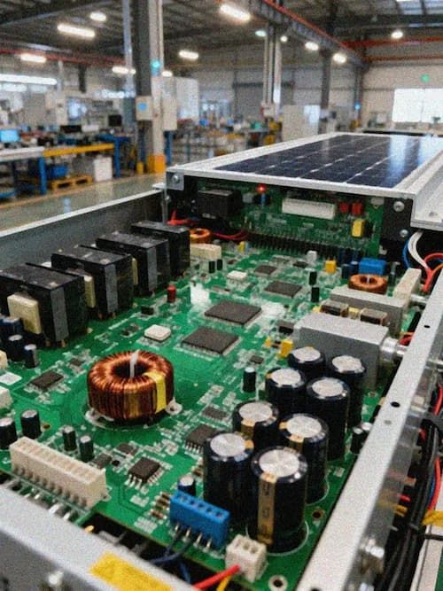
In renewable energy conversion equipment such as solar photovoltaic inverters, wind power converters, and energy storage systems, printed circuit boards (PCBs) are far more than simple interconnect carriers; they are the key hardware foundation determining the energy conversion efficiency and long-term operational reliability of the entire system. Their design must directly address multiple challenges, including high voltage, high current, wide temperature range, strong electromagnetic interference, and harsh environments. This article, based on industry technical specifications and engineering practices, systematically elaborates on the core elements of PCB design for efficiency and reliability.
High Power Handling Capacity: The Physical Basis of Efficiency
Renewable energy conversion systems generally operate in high power density scenarios. For example, residential photovoltaic inverters need to handle DC inputs of over 600 V, while utility-scale systems can reach 1500 V; wind power converters need to cope with continuous high current outputs under extreme environments. This directly determines the PCB's current carrying capacity and thermal management efficiency, both of which together constitute the prerequisite for ensuring efficiency.
Heavy Copper Design: To reduce line resistance (R) and Joule heat (P = I²R) loss, copper foil thickness far exceeding the conventional 1 oz (35 μm) is necessary. Recommended solutions include 2 oz (70 μm) copper thickness for main power circuits. Some critical scenarios (such as the Battery Management Unit (BMS) acquisition board) require copper thickness ≥35 μm, or even up to 70 μm. New energy vehicle 800 V high-voltage platforms commonly use 3–6 oz (105–210 μm) ultra-thick copper designs, which can reduce resistance by more than 60% at the same line width.
Wideer Traces and Larger Copper Areas: High-current paths (such as DC buses and inverter bridge arms) require a line width ≥3 mm, supplemented by large copper areas, forming a low-impedance, high-heat-dissipation "copper strip". For higher requirements, a grid copper design (e.g., line width/spacing = 0.5 mm/0.3 mm) combined with densely packed grounding vias at nodes can reduce temperature rise by 15 °C and thermal deformation by 22% in actual measurements.
Stepped Copper Thickness Transition: In areas of abrupt copper thickness change (e.g., 4 oz → 3 oz), a gradual transition design with a length ≥ 5 mm can significantly reduce the thermal stress concentration factor from 3.2 to 1.8, greatly improving thermal cycling reliability.
Advanced Thermal Management: The Core Defense for Reliability
High power conversion inevitably involves significant heat generation. If heat cannot be dissipated in time, it will lead to accelerated component aging, solder joint failure, substrate delamination, and ultimately system failure. Therefore, "heat dissipation design" is a core strategy throughout the entire PCB lifecycle.
Selection of High Thermal Conductivity Substrate: Abandoning standard FR-4, materials with a thermal conductivity > 1 W/m·K are preferred. Specifically, this includes:
- Aluminum substrate (Metal Core PCB): Provides excellent lateral thermal conductivity and is commonly used for power module heat dissipation;
- Ceramic substrate (DBC, AlN): Possesses extremely high insulation and thermal conductivity, suitable for high-voltage and high-frequency applications;
- High TG FR-4 (TG ≥ 170 °C): Maintains rigidity at 120 °C, with a 20% reduction in the coefficient of thermal expansion, ensuring dimensional stability;
- Polyimide (PI) or special ceramics: Meets long-term stability requirements in extreme temperature (-40 °C to +85 °C or even higher) and high-humidity environments;
Integrated active cooling structure: Plans heat dissipation paths at the PCB level, including adding thermal vents, using copper fill, optimizing the layout of heat-generating components (e.g., keeping power devices away from sensitive analog circuits), and reserving mechanical and thermal interfaces with external heat sinks (e.g., aluminum-based heat sinks).
Electromagnetic Compatibility (EMI/EMC) and Signal Integrity
IGBT/SiC switching devices in renewable energy equipment generate high-frequency, high dv/dt noise, which can easily be radiated or conducted through PCB traces, interfering with control signals and sensor acquisition, causing malfunctions or data distortion. Therefore, EMI/EMC design is the "invisible guardian" of reliability.
Layered and Shielded Design: Employing a multi-layer board structure (commonly 4–8 layers), independently planning the "Power Plane" and "Signal Plane," utilizing a complete ground plane as a shielding layer. High-end solutions employ a four-layer board design (signal/ground/power/shielding layer), physically isolating high and low voltage areas, and embedding copper-based heat sinks to simultaneously reduce thermal resistance and EMI.
Filtering and Impedance Control: Integrating π-type filter circuits and common-mode inductors at the power input and critical signal paths, and performing precise impedance matching (such as differential pair wiring, 50 Ω single-ended impedance control) to suppress conducted and radiated interference at the source. Medical imaging equipment employs a 20-layer high-frequency PCB design with a shielding layer to achieve precise impedance control.
Process-level Protection: For mixed-signal and low-voltage PCBAs, SCH (Signal & Control Hybrid) isolation design optimization is implemented in corrosive environments, and the conformal coating process is strengthened to improve the overall protection level.
Environmental Adaptability and Manufacturing Reliability
Renewable energy equipment is often deployed in harsh environments such as outdoor rooftops (photovoltaics) and high-altitude/offshore (wind power), facing challenges such as wide temperature ranges, high humidity, salt spray, and vibration. PCB reliability must be comprehensively reinforced from materials and processes to structure.
Wide Temperature Range Material System: Both the substrate and surface treatment must meet an operating temperature range of -40 °C to +85 °C (or even higher). Surface treatment processes must be highly reliable, such as immersion gold (ENIG), immersion tin, or OSP, to ensure soldering reliability and corrosion resistance.
High Reliability Structure and Process: Utilizing HDI (High Density Interconnect) technology to achieve fine lines and micro-vias, improving integration and signal transmission performance; for industrial applications, a minimum line width/spacing of ≥8 mil (0.2 mm) is recommended, with critical signal lines thickened to 12–15 mil; 2 oz copper foil is recommended for the power layer.
Redundancy and Diagnostic Design: On critical control boards (such as the VBE main control board of UHVDC transmission systems), a dual-system parallel design, hot/cold standby redundancy architecture is employed, along with integrated self-diagnostic pins to ensure stable operation under complex conditions.
From Single-Point Design to Systems Engineering Energy conversion PCB design has transcended the traditional scope of electrical connections, evolving into a systems engineering approach integrating power electronics, thermodynamics, electromagnetics, and materials science. Its ultimate goal is to build a "digital heart" capable of continuous operation for decades in harsh environments while ensuring ultra-high conversion efficiency (through low-resistance, low-heat design). This requires designers to not only be proficient in PCB layout, but also to have a deep understanding of end-application scenarios, system-level constraints, and full lifecycle reliability verification methods. Only in this way can we truly empower the efficient, safe, and sustainable development of green energy.